Andy’s method
The technique described by Andy in his article High Resolution without gb.display is relatively simple but terribly clever. The general idea is to render the graphics in a buffer zone in memory, before dumping it to the interface bus of the TFT screen. Nevertheless, he starts from the observation that the Gamebuino META does not have enough memory (its RAM being limited to 32 KB) to be able to contain a high-resolution screen-size buffer with a 16-bit color depth (the necessary memory is 40 KB). This is the reason why you cannot use gb.display.
He therefore proposes to cut out the rendering surface to be calculated in sufficiently small slices, so that they can be contained in RAM in turn, in the form of a small buffer. The rendering calculation is thus performed on this buffer, and once the calculation is completed, the buffer is then copied to the screen for display. Then we move on to the next slice, and so on… If the partial rendering cycle (calculation + copy to the screen) of each slice is fast enough, the complete scene of the game can then be displayed without being able to distinguish each of the successive steps.
Andy’s brilliant idea is to use the DMA controller to make transfers between the memory and the display device. The acronym DMA stands for Direct Memory Access. It is indeed possible to transfer the data directly through a dedicated controller between the main memory and the display device. This process only involves the processor to initiate and conclude the transfer through interruptions. Therefore, DMA transfer offers a faster way to exchange data blocks between memory and display. The icing on the cake: while the transfer is being made, the processor is at rest. It can therefore be used to perform other tasks in parallel! And that’s where all the magic of this technique works…
Indeed, we have to handle 2 buffers in parallel: while the processor is busy calculating the rendering on the first buffer, the DMA controller is in charge of transferring the second one to the screen . And it is precisely by using gb.tft that we will be able to perform these operations in our C++ code.
Implementation
You are free to organize the cutting of the whole rendering surface by delimiting the slices as you wish. All you have to do is determine the most appropriate layout for the rendering you need to achieve. The simplest methods (but not necessarily the most efficient, as the case may be) consist in cutting the rendering surface into regular horizontal or vertical slices.
Throughout this tutorial, we will rely on a horizontal slicing. Each slice will cover the total width of the screen, over a height of 8 pixels. We can therefore calculate the size needed to allocate in memory to accomodate a buffer corresponding to each of these slices:
Buffer size: (160 x 8 pixels) x (16 bits) = 20,480 bits = 2,560 bytes = 2.5 KB
As we have to handle two buffers in parallel, we will only need to allocate 2 x 2.5 = 5 KB of memory to be able to calculate the complete game scene in full 16-bit color… That’s great, isn’t it?
The implementation is therefore quite simple: it will be enough to scan all the slices one by one, and for each new slice, we will alternate bit writing on buffer 1 or buffer 2.
What should we write on the buffer? Well, for each (x,y) point of the current slice, we will have to determine the color of the pixel that will be displayed at that position. We will therefore report on the buffer the value of the 16-bit integer corresponding to this color.
To determine the color of the pixel to be displayed, it will be sufficient to browse all the graphic assets of the game scene and determine which ones have a non-empty intersection with the current slice. All that remains is to project the coordinates (x,y) into the repository of each graphic asset to pick the color code to be copied into the buffer. The graphic assets will be browsed in the order of the display stack (from the farthest to the nearest). We could even try to optimize things because a pixel of depth n necessarily masks all pixels whose depth is greater than n. It is therefore unnecessary to explore all pixels of graphic asset with a depth greater than n.
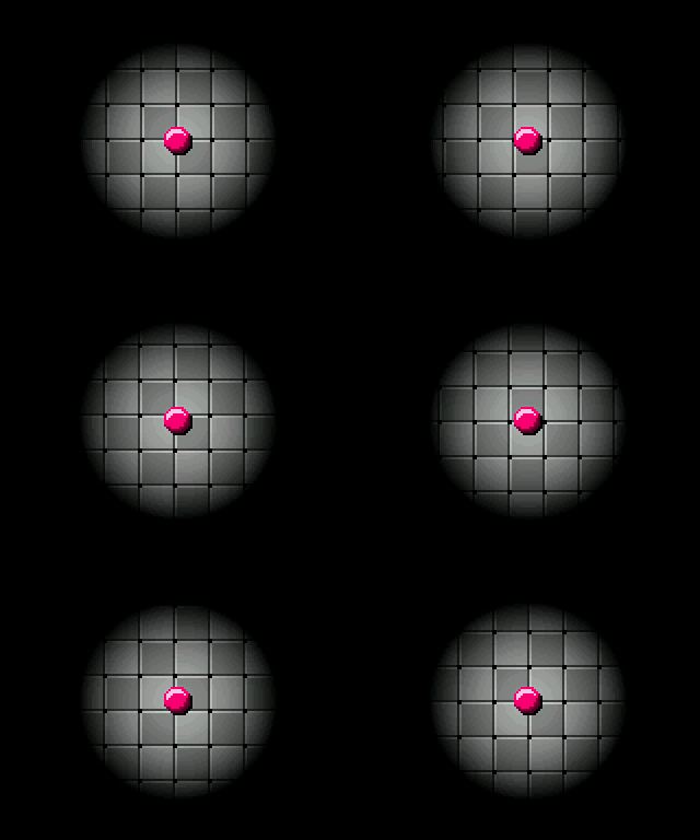
Here is a small animation illustrating the rendering process for a very simple game scene where only the ball is present:

Important note
The order in which the bytes are organized in memory differs depending on whether they are intended for the CPU or the TFT display! This order is referred to as endianness.
When the META CPU stores a 16-bit integer in memory, for example
0xA3B7in hexadecimal notation, it stores it in bytes in reverse orderB7 A3for a memory structure based on a 1-byte atomic unit and 1-byte address increment. Thus the least significant byteB7is stored at the smallest memory address (the lowest weight first). The higher byteA3is stored at the next memory address, and so on. Architectures that follow this rule are called little-endian.In the case of the TFT display, it is exactly the opposite: the most significant byte
A3is recorded at the lowest memory address. The lower byteB7is stored at the next memory address, and so on. Architectures that follow this rule are called big-endian.It will therefore be necessary to remember of inverting bytes two by two when writing in the buffer that is intended to be sent to the screen (through the DMA controller), otherwise the displayed colors may not correspond to those expected!

